Jumat, 23 Februari 2018
Asus K55VD - backlight doesn't work
Asus K55VD - backlight doesn't work
I have a problem on the backlight of asus k55vd. The backlight doesn't work all the time (probably because of liquid spill on the power module). Sometimes it's working but it doesn't light up the whole backlight matrix, sometimes it doesn't light up at all. Playing around the power module with a magnet dose the trick, but it's seems it's only temporary, and doesn't always work. Right now it's working and i did some measurements. Legend: Blue -> backlight on; Red -> changed value when the backlight is off
Plate: E89382 HannStar J MV-4 94V-0 rev 3.0. Could not find schematics / electric diagram.
Made the folowing measurements on J4601: 20, 21, 23, 24, 25 according to this topic: (see "lcd" picture).

40
39 GND
38 GND
37 GND
36 GND_AUDIO
35 INTMIC_P
34 GND
33 GND
32 GND
31 USB_PP9_C
30 USB_PN9_C
29 +5V_CAM
28
27
26
25 +LED_VCC_INV
24 +LED_VCC_INV
23 +LED_VCC_INV
22
21 LED_BKLTEN
20 LED_BKLTCTL
19 GND
18 LVDS_LCLKP_PCH
17 LVDS_LCLKN_PCH
16 GND
15 LVDS_L2P_PCH
14 LVDS_L2N_PCH
13 GND
12 LVDS_L1P_PCH
11 LVDS_L1N_PCH
10 GND
9 LVDS_L0P_PCH
8 LVDS_L0N_PCH
7 EDID_DAT_PCH
6 EDID_CLK_PCH
5
4 +3VS_C
3 +3VS_LCD
2 +3VS_LCD
1
Measurements on the power module:
Once I got the same "backlight on" measurements (blue) on the power jumper (J6801) and the LCD backlight was off. So I am not sure where is the problem.

Here is the power jumper on the PCB:

Could not find a datasheet for D6806

I can't guarantee the info provided is 100% accurate
I already ordered a new power module, still waiting for it.
Thank you and sorry for my bad english.
EDIT: The hall sensor seems to work because
- the power button dose not work when a magnet is present
- is switching the backlight on and off
Selasa, 20 Februari 2018
TIPS Aman Modifikasi Power Supply
TIPS Aman Modifikasi Power Supply
Kadang kala kita mendapatkan problem yang sulit ,pada saat memperbaiki power supply
kita sering mendapat kenyataan bahwa spareparts sudah discontinued,kalaupun ada biasanya produk ASPAL(Asli tapi Palsu).
Contohnya IC regulator Toshiba TEA2164 ,dan banyak lagi contoh yang lainnya .
Atau juga kita kadang kala menemui kendala ,dimana regulator yang kita perbaiki baru dicolokan ke jala jala PLN ,transistornya langsung meledak !
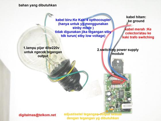
Untuk mengatasi hal tersebut diatas ,kita bisa menyiasatinya dengan rangkaian semi-closed switching power suply .Seperti yang ada pada gambar diatas.
Bahan Yang dibutuhkan :
- Semi-closed switching power supply(universal power supply)
- Lampu pijar 40w 220v (bohlam )
- Diode R2M –R2KY.
- Kabel 5cm (untuk jumper ).
- Perhatikan tegangan output yang dibutuhkan oleh rangkaian ,apakah ,90v, 110v atau 125volt .
- Hubungkan kabel merah dari modul universal power supply ke kaki dari transistor yang dilepas ,atau ke drain FET atau Pin 1 IC power Reg ,yang penting terhubung ke kaki dari trafo switching yang terhubung ke VCC 300V.
- Hubungkan kaki hitam ke negatip atau ground elco besar (220uf300v ).
- HUBUNGKAN KABEL WARNA BIRU KE KAKI 4 OPTOCOUPLER ,JIKA RANGKAIAN MENGGUNAKAN SYSTEM STANDBY LOW VOLTAGE ,atau tegangan B+ turun jika posisi stby ,Kaki 3 optocoupler digroundkan saja
- Hubungkan lampu pijar ke rangkaian output power supply 110volt (di elco 220uf/160v) atau bisa juga di colektor transistor horizontal out ,dan yang satu kabel lagi ke ground atau negative.
- Hubungkan kabel jumper ke basis dan emitor transistor horizontal output,gunanya untuk menonaktipkan tr horizontal out .
- PUTAR TRIMPOT MODUL UNIVERSAL POWER SUPPLY KE POSISI MINIMUM (DIPUTAR KE ARAH KIRI !)
- HUBUNGKAN AC CORD (JEK AC ) KEJALA JALA PLN . LAMPU PIJAR HARUS MENYALA ,BILA TIDAK PERIKSA SESUAI URUTAN DIATAS
- UKUR TEGANGAN DI OUTPUT 110 VOLT ATAU DI KAKI DARI LAMPU PIJAR ,
- SESUAIKAN TEGANGAN OUTPUT YANG DIINGINKAN DENGAN MEMUTAR TRIMPOT (WARNA KUNING).BILA TEGANGAN YANG DIBUTUHKAN 125 PUTAR TRIMPOT DAN AMATI DI AVO METER SAMPAI MENUNJUKAN ANGKA 125 VOLT. LIHAT PERUBAHAN DI LAMPU PIJAR
- LEPASKAN JEK AC ,LEPASKAN JUGA LAMPU PIJAR.PASANG DIODE R2M ATAU R2KY TERGANTUNG DARI RANGKAIAN YANG DIBUTUHKAN ,JIKA B+ 110 VOLT MAKA R2M YANG DIPASANG ,JIKA B+125VOLT ,R2KY YANG DIPASANG .DIPASANGNYA DI KAKI ELCO 220UF160VOLT !
- LEPASKAN JUMPER YANG MENGHUBUNGKAN BASIS EMITOR TRANSISTOR HORIZONTAL OUT .
- NYALAKAN TVNYA DAN AMATI APAKAH LEBAR GAMBARNYA SUDAH NORMAL?,JIKA MENYEMPIT MAKA TEGANGAN OUTPUT HARUS DISESUAIKAN LAGI DENGAN MEMUTAR TRIMPOT WARNA KUNING ,(HARUS HATI HATI karena sangat SENSITIP).
Modifikasi PSU TV LCD Sharp Aquos Pakai Gacun
Modifikasi PSU TV LCD Sharp Aquos Pakai Gacun
Beberapa hari yang lalu saya mengalami kebingungan masalah servis TV LCD Sharp Aquos. Dimana kerusakan utamanya adalah pada PSU (Power Supply). TV tersebut tidak bisa nyala sama sekali atau bisa dikatakan mati total. Setelah dicek ternyata kerusakannya dibagian IC driver dengan tipe FAN6754MR. Kenapa bisa saya mengklaim IC tersebut yang rusak?. Jujur saja sebenarnya power supply SMPS seperti ini saya belum mahir. Bisanya cuma ngecek komponen-komponen saja. Pada rangkaian PSU tersebut saya dapati sekring yang putus di dekat IC tersebut, nah kalau saya ganti baru putus lagi. Alhasil saya copot IC tadi dan saya ukur kakinya kok pada short alias konslet. Dari sinilah saya nyatakan komponen tersebut rusak. Akhirnya saya putuskan untuk mencari ICFAN6754R ke toko elektronik terdekat. Namun sayang hasilnya nihil, sebab toko elektronik didaerah saya kurang lengkap. Oleh sebab itu saya googling di internet mengenai permasalahan tersebut. Sampai akhirnya saya menemukan beberapa blog yang membahas hal ini dengan mengganti IC tersebut dengan Gacun. Setelah saya telusuri ternyata sumbernya dari situsnya hamimservis.com. Jadi langsung saja dipraktekkan modifikasi PSU TV LCD sharp aquos pakai gacun.

Tahap pertama sebelum memasang gacun adalah:
- Pastikan IC FAN6754MR sudah dicopot.
- Kemudian siapkan sebuah kabel untuk menghubungkan jalur tegangan 24 volt dari PSU asli ke B+ gacun.
- Copot 2 buah dioda 4148 yang ada didekat trafo gacun.
Setelah tahap diatas selesai, maka langkah selanjutnya adalah memasang si Gacun tadi ke power supply TV. Untuk caranya adalah sebagai berikut:
- Kabel merah pada Gacun dihubungkan ke kaki colector trafo atau bekas untuk kaki tengah IC Fan6754MR tadi.
- Selanjutnya kabel hitam dihubungkan ke ground trafo atau kaki min elco yang paling besar dekat sekring yang putus tadi.
- Lalu kabel biru dihubungkan ke octocoupler untuk sistem feedback control.
- Kemudian tambahkan satu kabel lagi di bekas copotan dioda 4148 atau B+ gacun dengan jalur tegangan 24V di PSU.
Jika bingung silahkan lihat gambar yang saya jepret dibawah ini.

Setelah semua terhubung dengan baik, maka langkah selanjutnya adalah mencobanya. Ternyata hasilnya TV bisa menyala dengan normal kembali. Nah itulah modifikasi kali ini, mudah-mudahan bermanfaat dan sebelumnya admin juga ucapkan terimakasih kepada hamimservis yang telah share tipsnya. Selanjutnya silahkan baca juga Modifikasi TV Sharp yang hilang suara tapi gambar ada.
Sumber : http://www.masputz.com/2016/03/modifikasi-psu-tv-lcd-sharp-aquos-pakai.html
Sumber : http://www.masputz.com/2016/03/modifikasi-psu-tv-lcd-sharp-aquos-pakai.html
Minggu, 18 Februari 2018
How to repair broken touchpad connector on motherboard
How to repair broken touchpad connector on motherboard
In this post I explain how to repair broken touchpad cable connector on a motherboard.
Let’s say you were fixing a laptop yourself and accidentally damaged the touchpad connector or any other similar connector. The problem is the touchpad connector soldered to the motherboard and it’s impossible to replace it with regular soldering tools. Also, these connectors are not sold separately which makes the replacement even more impossible.
Let’s try to repair it. We’ll do it using the same technique as for fixing the keyboard connector.
On the following picture you see a typical touchpad connector. The connector has а white base (permanently attached to the motherboard) and locking tab (moving part).
In order to unlock the connector you lift up the left side of the locking tab. The locking tap opens up at a 90 degree angle and releases the touchpad cable. After that you pull the cable from the connector.

On the following picture you see the damaged connector. I wasn’t careful enough and separated the locking tab from the base.
Unfortunately there is no way to attached broken tab back.

Here’s how I fixed it.
Insert the touchpad cable back into the connector. The touchpad cable has contacts on the bottom side – the side which is facing the motherboard.
In order to work properly the cable contacts have to touch contacts inside the connector but it’s not happening when the locking tab is missing.

Find a small piece of plastic. It has to fit inside the connector and be thick enough to fit tightly between the four metal hinges and touchpad cable.
Insert this piece of plastic into the connector. Make sure the touchpad still seated inside.

On the following picture you see the connector “fixed”. It doesn’t look the same as before but nevertheless the cable secured inside.
The piece of plastic applies pressure on the cable and it makes good connection with the contacts. The touchpad works again!
Now you can secure the connection with tape.
This simple trick fixed my touchpad.

Here’s another type of touchpad connector.
The locking tab is broken and also separated from the base.

Position the broken tab the way it was plugged before but do not push it into the connector yet.

Now insert the cable. In most cases it goes under the tab.
Push the cable all the way into the connector.

While holding the cable, push the tab into the connector.
Even though the locking tab is broken, it should secure the cable.
Again, apply some tape over the connection to secure it.

Link Ref : http://www.laptoprepair101.com/how-to-repair-broken-touchpad-connector-on-laptop-motherboard/
Sabtu, 17 Februari 2018
Dell Inspiron 6000 Screen Replacement
Dell Inspiron 6000 Screen Replacement

Introduction
Replacing the screen takes some time and effort, but requires few tools.
Step 1
Battery
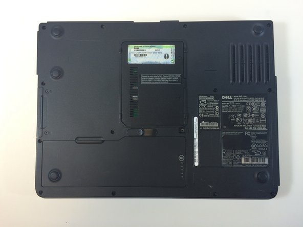
- Flip the laptop over, bottom-side up.
- Push the switch next to the battery.
- At the same time, lift the battery away from the laptop.
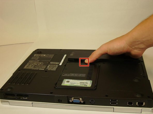
Step 3 Keyboard
- Place the laptop on flat surface.
- Carefully open the laptop at far as it will go so that the back of screen is touching the flat surface.
- Carefully take a spudger and separate part of the cover at the red circle.


Step 4
- Remove two 4 mm Philips #00 screws.

Step 5
- Gently lift the keyboard away from the laptop without harming the cord that is located at the bottom of the keyboard.

Step 6
- Gently pull the blue tab up until it comes away from computer.

Step 7 Screen
- Remove one 4mm Philips #00 screw to completely disengage blue tab.

Step 8
- Pull and disconnect the blue tab.

Step 9
- Disconnect the black and white wires.

Step 10
- Remove four 4mm Philips #00 screws at the hinges for the screen.

Step 11
- Separate the top panel of the laptop from the bottom panel.

Step 12
- Use the plastic opening tools to remove the six rubber screw covers in the corners.
- Remove six 4 mm #00 Philips screws located in the corners.


Step 13
- Insert the plastic opening tools between the screen holders.
- Go completely around the screen, separating the screen holders with the plastic opening tools.


Step 14
- Remove 12 4mm #00 Philips screws at the perimeter of the screen.


Step 15
- Gently lift the screen from the holder.


Repair LCD screen with water damage
Repair LCD screen with water damage
Yesterday took apart and repaired my notebook LCD screen with water damage. The screen itself was working just fine but it had two different problems.
– previous owner spilled water on the laptop. Somehow the water got inside the LCD screen and left stains inside the screen. The water marks were very noticeable on a white background and it was very irritating.
– the screen also had dust and lint inside also very noticeable on a white background. I have no idea how it got in there but I decided to clean it up too.


To fix both problems I had to open up the LCD screen. This was my first experience on opening a notebook screen. I was pretty confident because I didn’t really care if I break the screen, I just wanted to know if it’s possible to fix it.
Warning: the LCD screen can be easily damaged if you open it up. If you do something wrong the screen might become completely unusable and you’ll have to buy a new screen. It’s very expensive. Think twice before you decide opening the screen. Continue at your own risk.
Here’s my Dell Latitude D610 notebook with water damaged screen I’m going to take apart.
First of all remove the battery from the notebook.
Lift up rubber screw seals and remove all screws.
Carefully separate the screen bezel from the LCD cover and remove the bezel.
Remove two screws from the front and two screws from both sides.
Carefully remove the LCD screen from the cover and place it on the notebook base. Disconnect the video cable and the inverter board cable.
On this model the inverter board is attached to the screen with two screws. Remove both screws, disconnect the screen cable and remove the inverter board.
Carefully peel off sticky tape and foil and put it aside. You’ll have to put it back in place during the screen reassembly.
Remove two screws from both sides of the screen.
Carefully place the screen upside down on a flat surface. Carefully unglue the film that covers the circuit board and remove two screws from the board (top circles). I wasn’t really sure if I have to remove screws on the bottom, so I removed them just in case. Do not touch the circuit board with fingers.
After both screws are removed you should be able to lift up the circuit board. Be careful, it’s still attached to the LCD.
Start unsnapping the metal frame from the screen. There are a lot of latches on all sides of the screen. You can unlock them with nails or a small flat head screwdriver.
After all latches are opened you should be able to separate the screen into three pieces: metal frame, LCD and background (not sure about correct technical name).
If you have lint or dust inside the screen, probably you’ll find it between the LCD and the background. Do not touch LCD or background with your fingers. I was able to remove dust and lint up with a very soft cloth, barely touching the LCD and background surfaces.
After I split the screen I found that the background has a few some kind of optical layers (three transparent sheets) and in my case they were damaged by water. The water dried out and left stains between these optical layers.
In my case removing dust and lint wasn’t enough and I had to go further.
Very carefully separate the LCD with attached circuit board from the background.
To remove damaged optical layers it’s necessary to remove metal locks on both sides of the screen. It’s like a small clip that keeps layers in place.
After I removed both clips, I was able to look between the layers. At first I tried to clean up the dried water marks with a soft cloth but it didn’t help. The stains were still visible and didn’t want to go away.
Fortunately I had another similar screen laying around, it had a cracked LCD. I decided to borrow the optical layers from the cracked screen and transfer them to my screen. I wasn’t sure if it’s going to work, but as I mentioned before I didn’t really care if I break the screen. It was just an experiment.
So I disassembled the cracked screen and carefully transferred the white background and all transparent layers to my screen.
After that I assembled my screen back removing dust and lint with a very soft cloth. Breathlessly connected my new screen to the notebook. Turned it on and…
That’s a miracle, it works!
No dust, no lint, no water mars inside the screen! It’s clear and the background is absolutely clean!
My donor screen had a cracked LCD but it had a good working backlight tube. The backlght tube is very fragile and it’s located inside a metal casing. I didn’t remove the backlight tube, I just broke off the entire metal casing from the plastic frame. I’m going to use this backlight tube for testing purposes.